Speed Controlled Bike Light
Purpose
Cycling has many environmental and health benefits for individuals and communities that promote cycling. Unfortunately, our current transportation infrastructure often makes biking inaccessible and dangerous. That fear of riding alongside other vehicles is one of the biggest reasons people are hesitant to bike.1 Although we will need many policy and infrastructure changes to address this issue, my individual project is a technical solution that aims to make bikes more visible and increase the awareness of other road users. To do so, I’ve created a rear bike light that responds to the rider’s speed and tells road users when a cyclist is coming to a stop with a more visible brake light.
Overview
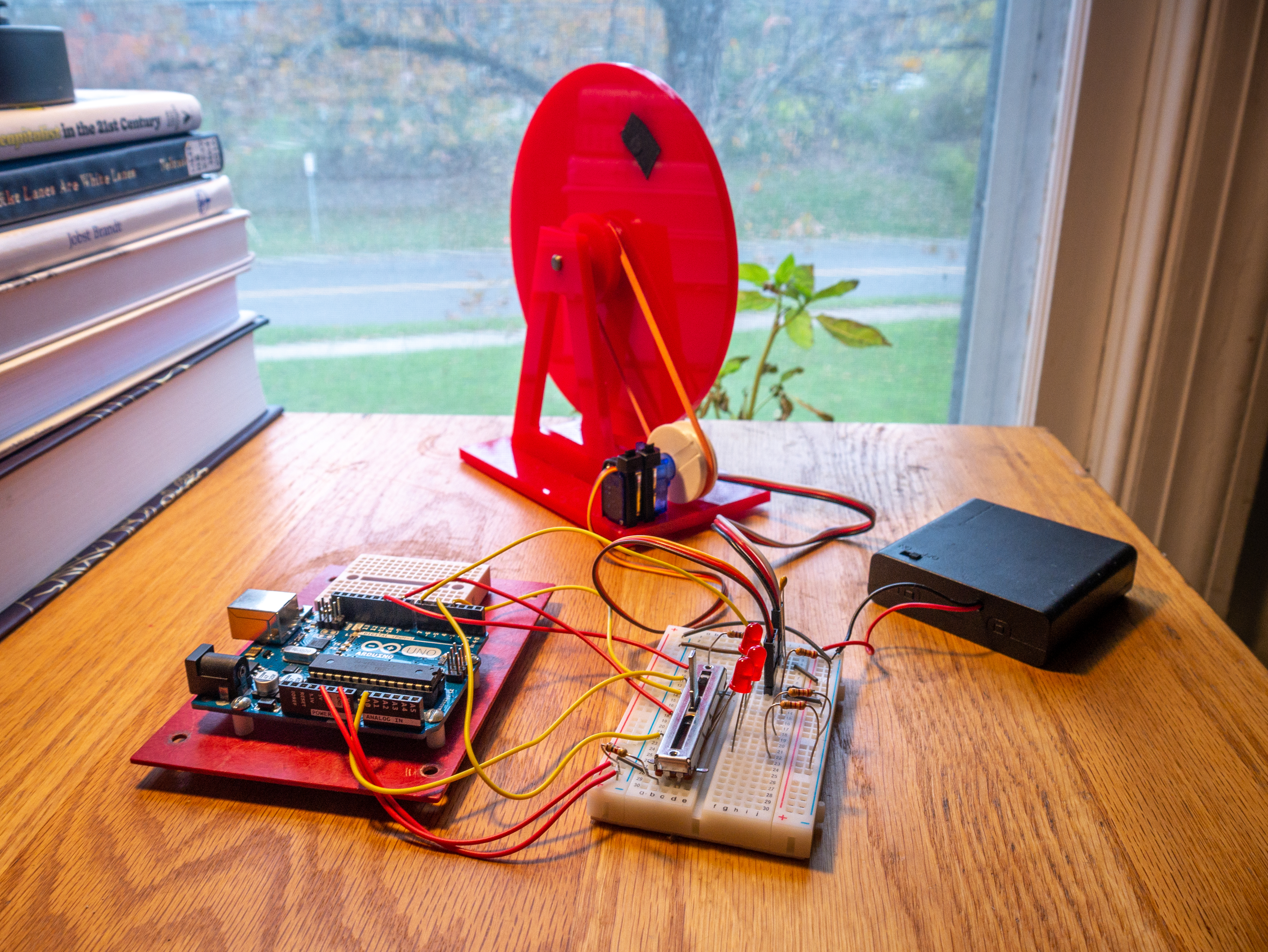
This project is a prototype of a speed-controlled bike light. Using a small wheel and a series of low-power LEDs, the setup demonstrates the measurement of speed with a magnet and hall sensor. Then, it responds with the LEDs by turning on a “brake light” when deceleration is detected.
To control the wheel, the Arduino monitors the voltage drop across a slide potentiometer using analog input pins. The Arduino then sets a 360-degree servo to a speed proportional to the potentiometer’s range. The servo is connected to the wheel with a rubber band and pulley. This setup allows the user to quickly change how fast the wheel rotates by adjusting the slide potentiometer. A small magnet is mounted to the rotating wheel. This is sensed by a hall sensor mounted to the frame supporting the wheel, and its output is directed into the Arduino.
Using an internal comparator, the Arduino translates the analog output of the hall sensor to a digital “on” when the output exceeds the internal 1.1V threshold.2 This happens asynchronously from the main Arduino program, so it’s able to consistently track when the hall sensor detects the magnet and records that time. The Arduino keeps a track of the time between these “pings” and records this period to a short list.
When updating the LED state, the Arduino references this list and compares the latest entry to previous entries to detect an increase in period. A large increase in the measured period indicates the wheel is decelerating and activates the solid braking light. After a few moments with no detected deceleration, the Arduino returns the LEDs to their normal flashing state.
Design Considerations
This design functions well as a prototype. However, there are several changes I would make to improve the reliability. The hall sensor, combined with the Arduino’s internal comparator, was difficult to tune and often gave inconsistent readings.
A reed switch of the correct sensitivity probably would have a been an easier sensor to work with for a similar price. The binary operation of the read switch would be easier to program around and likely less susceptible to interference.
If additional resources were available, it would be interesting to put the device into a form factor that could have been used on a bike. Creating an enclosure and using more powerful LEDs would make it more applicable to the road.
Assembly Instructions
The mechanical assembly is laser cut out of 0.25in acrylic and then assembled into the 3D structure. See Appendix C Fig.1 for part dimensions, and Appendix A for other materials.
The three smaller wheels should be glued to the 6” one about the same axis. The two 1.25” wheels should go next to the 6” one, and the 1.5” wheel on the other side of one of those to form a pulley where the rubber band can rest. Once the glue is dry, press in the bushings, tape the magnet into the small off-center hole, and loop the rubber band around the wheel pulley.
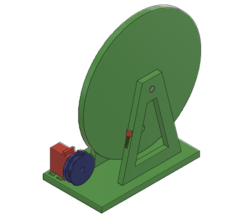
Once the wheel is assembled, place the triangular stands into the slots of the base and press the metal rod through them, supporting the wheel in the middle. Secure the stands to the base with glue, then attach the servo to the small slots in the base using zip ties. See Appendix C Fig. 3 for a view of the completed assembly.
The servo uses a 3D printed pulley (see Appendix C Fig. 2) to hold the rubber band. First, install the 2-pointed lever attachment included with the servo, then attach the pulley on top of that with one of the included screws.
Finally, tape the hall sensor to the stand at the same radius as the magnet, and wire the rest of the components as shown in Appendix B. The hall sensor may need to be adjusted slightly to ensure it detects the magnet consistently.
Operating Instructions
The only user input to the device is the slide potentiometer. Moving it along the track will increase and decrease the speed of the wheel. At steady speed and while increasing the speed, the lights flash normally. Then, when the speed is decreased suddenly, the lights go solid to indicate braking.
Download CAD and Code Files
Fly Wheel and Base to Laser Cut (DXF)
Appendix A: Bill of materials
| Source | Description | Part Number | Unit Price | Quantity | Price | |
|---|---|---|---|---|---|---|
| Purchased | 3D Printed Part | 3D Printed Servo Pulley | $3.32 | 1 | $3.32 | |
| Laser Cut Part | Laser Cut Wheel & Stand | $7.55 | 1 | $7.55 | ||
| DigiKey | Hall Sensor | 296-41083-1-ND | $1.50 | 1 | $1.50 | |
| DigiKey | Small Magnet | 469-1005-ND | $0.24 | 1 | $0.24 | |
| DigiKey | 10k Slide Potentiometer | PTA3043-2015CPB103-ND | $1.50 | 1 | $1.50 | |
| McMaster Carr | Rotary Shaft | 1327K113 | $3.61 | 1 | $3.61 | |
| McMaster Carr | Nylon Bushings | 6389K231 | $0.69 | 2 | $1.38 | |
| Scavenged Part | Zip Ties | $0.05 | 2 | $0.10 | ||
| Scavenged Part | Rubber Band | $0.05 | 1 | $0.05 | ||
| Adhesives | Tape & Glue | $0.00 | 3 | $0.00 | ||
| From Kit | Digikey | Arduino | 1050-1024-ND | $20.90 | 1 | $20.90 |
| DFRobot | 360 Micro Servo | SER-0043 | $3.90 | 1 | $3.90 | |
| Newark | Bread Board | 79X3922 | $2.71 | 1 | $2.71 | |
| Amazon: Austor | Wire Kit | ASIN : B07PQKNQ22 | $2.17 | 1 | $2.17 | |
| Digi-Key | Resistor 100 Ω | 100QBK-ND | $0.01 | 1 | $0.01 | |
| Digi-Key | Resistor 220 Ω | 220QBK-ND | $0.01 | 3 | $0.03 | |
| Digi-Key | Resistor 1k Ω | 1.0kQBK-ND | $0.01 | 1 | $0.01 | |
| Digi-Key | Capacitor 0.1uF | BC3324-ND | $0.07 | 1 | $0.07 | |
| Digi-Key | 3-Wire Extension | 1568-1930-ND | $1.35 | 1 | $1.35 | |
| Jameco | Red LED | 697602 | $0.05 | 3 | $0.15 | |
| monoprice | USB Cable A to MicroB | 4867 | $0.89 | 1 | $0.89 | |
| McMaster-Carr | AA Batteries | 71455K58 | $0.40 | 4 | $1.62 | |
| Jameco | 4-AA Battery Holder | 216187 | $1.75 | 1 | $1.75 | |
| DigiKey | 3-Pin Header M-M | 3M156516-03-ND | $0.58 | 2 | $1.16 | |
| Totals | Purchased | $19.25 | ||||
| From Kit | $36.72 | |||||
| Total | $55.97 |
Appendix B: Circuit Diagram
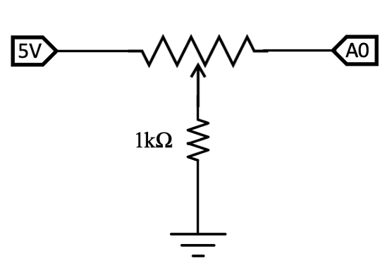
The circuit diagrams are broken up into three separate sections. Both the hall sensor and servo are run off the 6V battery pack but communicate with the Arduino. The LEDs and potentiometer are both powered by the 5V Arduino and use input pins but are otherwise discrete circuits.
Fig. 1: Servo and Hall Sensor (6V) Circuit, with Arduino Pins 7 & 11
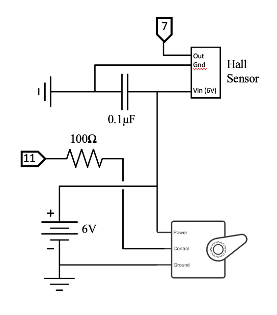
Fig. 2: LED Circuit, with Arduino Pins 9, 3, & 5
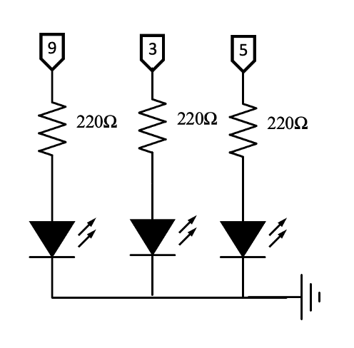
Fig. 3: Slide Potentiometer, with Arduino Analog Pin A0
Appendix C: CAD Files and Drawings
Fig. 1: Outline for Mechanical Assembly, Laser-cut 0.25” Acrylic
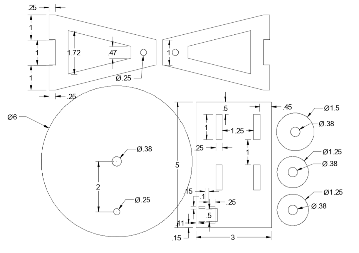
Fig. 2: Servo Pulley, 3D Printed PLA
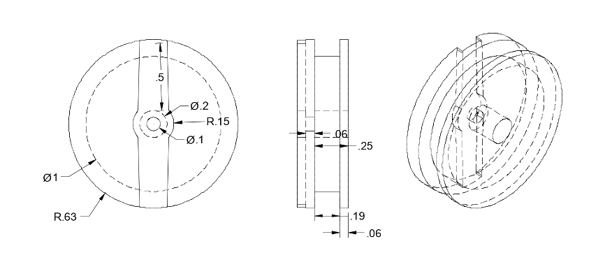
Fig. 3: Overall Assembly, Including Servo and Hall Sensor (Red)
Appendix D: Arduino Code
/*
 * Speed Controlled Bike Light
 * Mechatronics Individual Project, Gabriel Ewig gre27
 *
 * This project is a prototype of a speed-controlled bike light.
 * Using a small wheel and a series of low-power LEDs,
 * the setup demonstrates the measurement of speed with a magnet and hall sensor,
 * and response of the LEDs by turning on a “brake light” when deceleration is detected.
 *
 * This code has two main components: a main loop that sets the servo speed and LED state,
 * and a interrupt that triggers when the hall sensor detects the magnet and exceeds 1.1V.
 * The arduino keeps track of the period between these "pings", and activates the brake light
 * if the period increases, indicating deceleration.
 */

#include <Servo.h>

// Setup servo
Servo wheel_servo;

// Create global variables for the wheel speed, and state triggering
int period[2]; // Stores past two period measurements
int last_ping; // Temporary storage of last ping time to filter double-count
int brake_trigger; // Count down to keep brake on after trigger
String state = "normal"; // State name, for serial reference
bool led = false; // Helps toggle LEDs on/off


// Define digital pins that are connected
int led1 = 9;
int led2 = 3;
int led3 = 5;

void setup() {
  Serial.begin(9600); // Start debugging info to serial

  // Set pin mode
  pinMode(led1, OUTPUT);
  pinMode(led2, OUTPUT);
  pinMode(led3, OUTPUT);
  pinMode(A0, INPUT);

/* Setup an analog interrupt on pin 7.
 * This detects when the output of the hall sensor is rising, and triggers the ISR function.
 * This uses the internal arduino comparator, and triggers if the voltage exceeds 1.1V.
 * This method of interrupts allows the speed to be more responsive, while also continuously updating the light behavior.
 */
  pinMode(7,INPUT);
   ACSR = B01011010;

  // Attach servo
  wheel_servo.attach(11);

  // Initially, set all LEDs to full brightness.
  analogWrite(led1, 255);
  analogWrite(led2, 255);
  analogWrite(led3, 255);
}

ISR(ANALOG_COMP_vect) {
  // This is an interrupt function that is called when the the magnet begins to be sensed.
  // The function compares the current time to the last recorded time, and adds that period to the period list.
  int temp = millis() - last_ping;
  //Serial.println("Hall!");
  if (temp > 200){ // Prevents double counts if magnet is slow. At these speeds, the period is always > 200ms.
    last_ping = millis();
    period[1] = period[0];
    period[0] = temp;
  }
}

void loop() {
  /*
   * STEP 1: Read potentiometer input and set servo speed proportionally.
   *
   * This potentiometer has non-linear resistance (see datasheet).
   * By dividing the range at 200 (about 60% of slide), the speed response is more natural feeling.
   * Each range has a different multiplying factor, to translate the pot reading (0-1024) to a servo speed (0-180).
   * Below pot=110, the very end of the range, the servo is stopped.
   *
   */

  int pot = analogRead(A0);
  int servo_speed;
  if (pot < 110) {
    servo_speed = 90;
  } else if (pot < 200) {
    servo_speed = 90 + pot*0.3;
  } else {
    servo_speed = 150 + (pot-200)*0.09;
  }
  wheel_servo.write(servo_speed);

  /*
   * STEP 2: Set light behavior based on recorded speed of wheel
   *
   * First, this checks if the brake was recently triggered, and continues to show the brake for a moment.
   * Otherwise, this checks if the last period increased from the previous one by over 80ms, and triggers a brake event if this is the case.
   * This sets the red lights to solid, and sets brake_trigger to 8 so that the light remains on for the next 8 loops.
   * In all other situations, the LEDs are toggled to create a flashing pattern.
   */

  if (brake_trigger > 0) { // Continued Braking State
    state = "braking-cont";
    analogWrite(led1, 255);
    analogWrite(led2, 255);
    analogWrite(led3, 255);
    brake_trigger--;
  } else if (period[1] - period[0] < -80){ // Detects deceleration and activates brake
    state = "braking";
    brake_trigger = 8;
    analogWrite(led1, 255);
    analogWrite(led2, 255);
    analogWrite(led3, 255);
  } else { // Normal flashing
    state = "normal";
    led = !led;
    if (led){
      analogWrite(led1, 255);
      analogWrite(led2, 255);
      analogWrite(led3, 255);
    } else {
      analogWrite(led1, 0);
      analogWrite(led2, 0);
      analogWrite(led3, 0);
    }
  }


  // Some helpful serial outputs
  //Serial.println("Pot: " + String(pot) + ", Servo: " + String(servo_speed));
  Serial.println("Speed: " + String(period[0]) + ", Last Speed: " + String(period[1]) + ", State: " + state);
  delay(250); // Delay. Effects flashing rate of LEDs, and slows down serial output.
}
-
“Four Types of Transportation Cyclists, Bicycle Counts, The City of Portland, Oregon.” Accessed October 6, 2021. https://www.portlandoregon.gov/transportation/article/158497. ↩
-
“Introduction to Arduino Interrupts and the ATmega328 Analog Comparator – Fiz-Ix.” Accessed October 26, 2021. http://www.fiz-ix.com/2012/01/introduction-to-arduino-interrupts-and-the-atmega328-analog-comparator/. ↩